
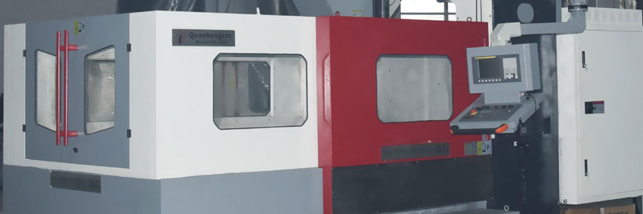
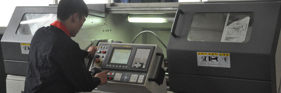
CNC milling machine is also called CNC Miller . CNC milling machine is an automatic machining equipment developed on the basis of general milling machines. The machining technology of the two is basically the same, and the structure is somewhat similar. CNC milling machines are divided into two categories: without tool magazine and with tool magazine. Among them, a CNC milling machine with a tool magazine is also called a machining center.
| Basic Information | System Specification | Fixture | Features |
| Programming Knowledge | Operating Procedures | Status Quo And Prospects | Basic Structure |
List of Contents
The Basic Information Of CNC Milling Machine
The Basic Information Of CNC Milling Machine
The development of science and technology and the rise and maturity of the world’s advanced manufacturing technology have put forward higher requirements on CNC machining technology; the application of ultra-high-speed cutting, ultra-precision machining and other technologies will affect the CNC system, servo performance, and spindle drive of CNC machine tools. , Machine tool structure, etc. put forward higher performance indicators; the rapid development of FMS and the continuous maturity of CIMS will put forward higher requirements for the reliability of CNC machine tools, communication functions, artificial intelligence and adaptive control technologies. With the development of microelectronics and computer technology, the performance of CNC systems is becoming more and more perfect, and the application field of CNC technology is expanding day by day.
The CNC milling machine is a CNC machine tool with strong processing functions. The rapidly developed machining centers and flexible processing units are all produced on the basis of CNC milling machines and CNC boring machines, both of which are inseparable from milling methods. Because the CNC milling process is the most complex and the technical problems that need to be solved are also the most, people have always focused on milling when researching and developing software for CNC systems and automatic programming languages.
The Emergence And Development Of CNC Machine Tools
With the rapid development of social production and science and technology, mechanical products are becoming more sophisticated and complex, and require frequent modification, especially the mechanical parts required in aerospace, shipbuilding, military and other fields, which require high precision, complex shapes, and small batches. Processing such products requires frequent modification or adjustment of equipment. Ordinary machine tools or highly specialized automated machine tools can no longer meet these requirements. In order to solve the above problems, a new type of machine tool-CNC machine tool came into being. This new type of machine tool has the advantages of strong adaptability, high processing accuracy, stable processing quality and high production efficiency. It integrates the technical achievements of electronic computer, automatic control, servo drive, precision measurement and new mechanical structure, and is the development direction of CNC machine tools in the future.
The Emergence Of CNC Machine Tools
The world’s first successfully developed CNC machine tool was a three-coordinate CNC milling machine, which was completed in 1952 by the American Parsons company (Parsons) and the Massachusetts Institute of Technology (MIT). As early as 1948, the United States put forward the initial idea of developing CNC machine tools when it was developing the task of processing machine tools for machining helicopter blade contour inspection templates. In 1949, with the support of the United States Air Force, Parsons officially accepted the commission and cooperated with the MIT Servo Mechanism Laboratory to begin the development of CNC machine tools. After three years of research, the world’s first experimental prototype of CNC machine tools was successfully trial-produced in 1952. This is a true line interpolation three-coordinate continuous control milling machine using the principle of pulse multiplier. Its control device consists of more than 2,000 electron tubes, which occupies the size of an ordinary laboratory. The birth of this CNC milling machine marked the beginning of the era of digital control in mechanical manufacturing.
CNC Milling Machine Processing
The processing surface shape of a milling machine is generally composed of straight lines, arcs or other curves. Ordinary milling machine operators according to the requirements of the drawings. Constantly changing the relative position between the tool and the workpiece, and then matched with the selected milling cutter speed, so that the tool can cut the workpiece, and then various workpieces of different shapes can be processed.
CNC machining is to divide the movement coordinates of the tool and the workpiece into the smallest unit quantity, that is, the smallest displacement. According to the requirements of the workpiece program, the numerical control system moves each coordinate by several minimum displacements, so as to realize the relative movement of the tool and the workpiece to complete the processing of the part.
Machining Center
In addition to the characteristics of ordinary milling machine processing, CNC milling processing also has the following characteristics:
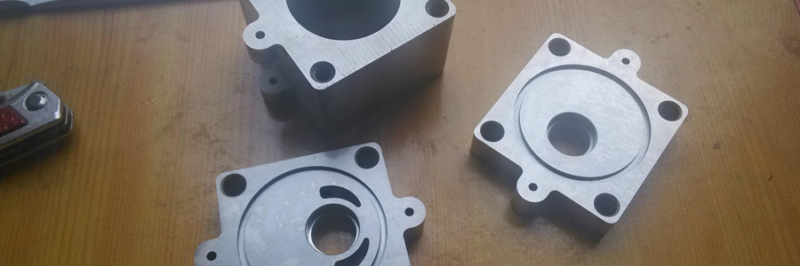
- The parts have strong adaptability and flexibility, and can process parts with particularly complex contour shapes or difficult to control size, such as mold parts, shell parts, etc.;
- It can process parts that can not be processed or difficult to process by ordinary machine tools, such as complex curve parts described by mathematical models and three-dimensional space surface parts;
- It can process parts that need to be processed in multiple processes after one clamping and positioning;
- The machining accuracy is high, and the machining quality is stable and reliable. The pulse equivalent of the numerical control device is generally 0.001mm, and the high-precision numerical control system can reach 0.1μm. In addition, the numerical control processing also avoids the operating errors of the operator;
- The high degree of production automation can reduce the labor intensity of the operator. Conducive to the automation of production management;
- The production efficiency is high. The CNC milling machine generally does not need special process equipment such as special fixtures. When replacing the workpiece, it only needs to call the processing program, clamping tool and adjustment tool data stored in the CNC device, thus greatly shortening the production. cycle. Secondly, the CNC milling machine has the functions of a milling machine, a boring machine, and a drilling machine, which makes the process highly concentrated and greatly improves the production efficiency. In addition, the spindle speed and feed speed of the CNC milling machine are continuously variable, so it is helpful to choose the best cutting amount;
The System Specification Of Cnc Milling Machine
The System Specification Of Cnc Milling Machine
Basic Structure
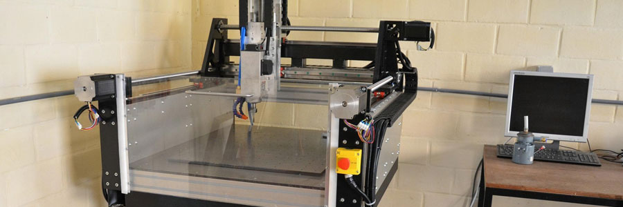
There are various forms of CNC milling machines. Although different types of CNC milling machines are different in composition, they have many similarities. The following takes XK5040A CNC vertical lifting table milling machine as an example to introduce its composition. ⅪSaw 040A CNC vertical lifting table milling machine is equipped with Ⅳ 4 3MA CNC system and adopts all-digital AC servo drive. The machine tool consists of 6 main parts. That is, the bed part, the milling head part, the table part, the horizontal feed part, the lifting table part, the cooling and lubricating part. The internal layout of the machine bed is reasonable and has good rigidity. There are 4 adjusting bolts on the base to facilitate the horizontal adjustment of the machine tool. The cutting fluid reservoir is located inside the machine bed.
Taxonomy
- Cooling system. The cooling system of the machine tool is composed of a cooling pump, a water outlet pipe, a water return pipe, a switch, and a nozzle. The cooling pump is installed in the cavity of the base of the machine tool. The cooling pump pumps the cutting fluid from the reservoir in the base to the water outlet pipe, and then passes it through The nozzle sprays out to cool the cutting area.
- Lubrication system and method. The lubrication system is composed of manual lubrication pump, oil separator, throttle valve, oil pipe, etc. The machine tool adopts a periodic lubrication method, using a manual lubricating oil pump to lubricate the spindle sleeve, vertical and horizontal guide rails and three-way ball screw through an oil separator to improve the service life of the machine tool.
From the point of view of the characteristics of digital control technology, because the CNC machine tool adopts the servo motor, and the application of digital technology realizes the direct control of the work sequence and movement displacement of the machine tool’s executive parts, the gearbox structure of the traditional machine tool is cancelled or partly cancelled, so the mechanical structure is also Greatly simplified. Digital control also requires the mechanical system to have high transmission rigidity and no transmission gap to ensure the execution of control commands and the realization of control quality. At the same time, due to the continuous improvement of computer level and control ability, it has become possible to allow more functional components on the same machine tool to perform various auxiliary functions required at the same time. Therefore, the mechanical structure of CNC machine tools has higher integrated functions than traditional machine tools. Claim.
From the perspective of the requirements of manufacturing technology development, with the emergence of new materials and new processes, as well as the low-cost requirements of market competition, metal cutting is moving towards higher cutting speeds and higher precision, higher and higher production efficiency and systems. Development in an increasingly reliable direction. This requires the CNC machine tools developed on the basis of traditional machine tools to have higher precision, more driving power, better dynamic and static stiffness and thermal stiffness of the mechanical mechanism, more reliable work, and can achieve long-term continuous operation and as little downtime as possible. .
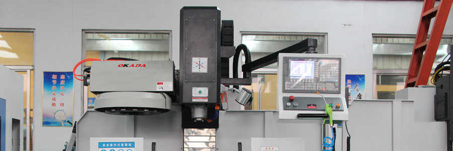
Milling Head Part
The milling head part is composed of two parts: a stepped (or stepless) gearbox and a milling head. The milling head spindle is supported on high-precision bearings. Ensure that the spindle has high rotation accuracy and good rigidity; the spindle is equipped with a quick-change tool nut, and the front cone adopts a taper of 1$0505; the spindle adopts a mechanical stepless speed change, its adjustment range is wide, the transmission is stable, and the operation is convenient. The brake mechanism can quickly brake the main shaft, which can save auxiliary time. When braking, the stop ring is opened by the brake handle to make the main shaft brake immediately. When starting the main motor, pay attention to loosen the spindle brake handle. The milling head component is also equipped with a servo motor, an internal toothed belt wheel, a ball screw pair and a spindle sleeve, which form a vertical direction (z direction) feed transmission chain to make the spindle move in a vertical linear direction.
The working table and the bed saddle are supported on the wide horizontal guide rail of the lifting table, and the longitudinal feed of the working table is driven by the servo motor installed at the right end of the working table. The precision ball screw is driven by the inner toothed pulley, so that the worktable can obtain longitudinal feed. The left end of the workbench is equipped with a hand wheel and a dial for manual operation. The longitudinal and longitudinal rail surfaces of the bed saddle adopt TuRcllE B plastic surface, which improves the wear resistance of the rail, the smoothness of movement and the retention of precision, and eliminates the phenomenon of low-speed crawling.
Basic Parts
The basic parts of a CNC milling machine usually refer to structural parts such as bed, column, beam, worktable, base, etc., which are relatively large in size (commonly known as large parts), and constitute the basic frame of the machine tool. Other parts are attached to the base part, and some parts need to move along the base part. Since the foundation piece plays the role of support and guidance, the original requirement for the foundation piece is good rigidity.
A frequency converter (Variable-frequency Drive, VFD) is a power control device that uses frequency conversion technology and microelectronics technology to control an AC motor by changing the frequency of the motor’s working power supply. In CNC machine tools, the frequency converter is mainly used to control the action of the spindle.
Headstock
Including the spindle box and the spindle drive system, which are used to clamp and drive the tool to rotate. The spindle speed range and output torque have a direct impact on processing.
Feed servo
Composed of a feed motor and a feed actuator, the relative movement between the tool and the workpiece is realized according to the feed speed set by the program, including linear feed movement and rotary movement.
Control System
The CNC milling machine motion control center executes the CNC machining program to control the machine tool for processing.
Assisting Equipments
Such as hydraulic, pneumatic, lubrication, cooling system, chip removal, automatic alarm and protection devices.
The Fixture Of Cnc Milling Machine
The Fixture Of Cnc Milling Machine
CNC machine tools are mainly used to process parts with complex shapes, but the structure of the fixtures used is often not complicated. The selection of fixtures for CNC milling machines can first be determined according to the batch size of the production parts. For single-piece, small-batch, and large-volume mold processing, positioning and clamping can generally be achieved directly on the worktable of the machine tool through adjustment, and then the position of the part can be determined by the setting of the processing coordinate system.
Knives
The cutting tools used on the CNC milling machine should be selected according to the material, geometry, surface quality requirements, heat treatment status, cutting performance and machining allowance of the processed parts, and choose the tools with good rigidity and high durability.
(1) Selection of milling cutter types
According to the geometry of the processed parts, the types of cutters selected are:
- 1) When machining curved parts, in order to ensure that the cutting edge of the tool is tangent to the machining contour at the cutting point, and to avoid interference between the cutting edge and the contour of the workpiece, a ball-end knife is generally used, a two-edge milling cutter for rough machining, semi-finishing and fine Four-flute milling cutter for machining.
- 2) When milling a large plane: In order to improve production efficiency and increase the surface roughness of the machined surface, insert-type disc milling cutters are generally used.
- 3) General-purpose milling cutters are generally used when milling small planes or stepped surfaces.
- 4) When milling the keyway, in order to ensure the dimensional accuracy of the groove, a two-edged keyway milling cutter is generally used.
- 5) Hole processing tools such as drills and boring cutters can be used for hole processing.
(2) Milling cutter structure selection
Milling cutters are generally composed of inserts, positioning elements, clamping elements and cutter bodies. Since the blade has a variety of positioning and clamping methods on the cutter body, and the structure of the blade positioning element has different types, there are many types of milling cutters and there are many classification methods. When selecting, it can be mainly based on the arrangement of the blades. The arrangement of blades can be divided into two categories: flat-mounted structure and vertical-mounted structure.
1) Flat mounting structure (the blades are arranged radially)
The structure of the cutter body of the plain-mounted milling cutter is good in manufacturability, easy to process, and can use non-porous blades (the blade is low in price and can be reground). Due to the need for clamping elements, a part of the blade is covered, the chip holding space is small, and the cemented carbide section in the direction of the cutting force is small, so the milling cutter of the flat-mounted structure is generally used for light and medium-weight milling.
2) Vertical mounting structure (tangential arrangement of blades)
The blade of the vertical milling cutter is fixed on the slot with only one screw, the structure is simple, and the indexing is convenient. Although there are fewer tool parts, the machining of the tool body is more difficult, and it is generally necessary to use a five-axis machining center for machining. Since the insert is clamped by cutting force, the clamping force increases with the increase of the cutting force, so the clamping element can be omitted, and the chip holding space is increased. Due to the tangential installation of the blade, the carbide cross section in the direction of the cutting force is large, so it can cut with large depth of cut and large cutting volume. This kind of milling cutter is suitable for heavy and medium-weight milling.
The angle of the milling cutter includes rake angle, relief angle, main deflection angle, secondary deflection angle, blade inclination angle and so on. In order to meet different processing needs, there are a variety of angle combinations. The most important of the various angles is the entering angle and the rake angle (the entering angle and rake angle of the tool are generally clearly stated in the product catalog of the manufacturer).
① Entering angle Kr
The entering angle is the angle between the cutting edge and the cutting plane. The entering angle of the milling cutter is 90°, 88°, 75°, 70°, 60°, 45°, etc.
The entering angle has a great influence on the radial cutting force and depth of cut. The size of the radial cutting force directly affects the cutting power and the anti-vibration performance of the tool. The smaller the entering angle of the milling cutter, the smaller the radial cutting force and the better the vibration resistance, but the cutting depth also decreases.
90° entering angle: It is selected when milling planes with shoulders, and is generally not used for pure plane machining. This kind of tool has good versatility (both processing step surface and flat surface), and it can be used in single-piece and small-batch processing. Since the radial cutting force of this type of tool is equal to the cutting force, the feed resistance is large, and it is easy to vibrate, so the machine tool is required to have greater power and sufficient rigidity. When processing a plane with a shoulder, a milling cutter with an entering angle of 88° can also be used. Compared with a milling cutter with a 90° entering angle, its cutting performance has been improved to a certain extent.
60°~75° entering angle: suitable for rough machining of plane milling. Since the radial cutting force is significantly reduced (especially at 60°), its vibration resistance has been greatly improved, and the cutting is smooth and light. It should be preferred in plane processing. The 75° entering angle milling cutter is a general-purpose tool with a wide range of applications; the 60° entering angle milling cutter is mainly used for rough milling and semi-finishing milling on boring and milling machines and machining centers.
45° entering angle: The radial cutting force of this type of milling cutter is greatly reduced, which is approximately equal to the axial cutting force, and the cutting load is distributed on the longer cutting edge. It has good vibration resistance and is suitable for boring and milling machines. Machining occasions with long spindle overhang. When this type of tool is used to process a plane, the blade breakage rate is low, and the durability is high; when processing iron castings, the edge of the workpiece is not easy to produce chipping.
②Rake angle γ
The rake angle of the milling cutter can be decomposed into the radial rake angle γf and the axial rake angle γp. The radial rake angle γf mainly affects the cutting power; the axial rake angle γp affects the chip formation and the direction of the axial force, when γp is When the value is positive, the chips fly away from the machined surface.
Commonly used rake angle combinations are as follows:
Double-negative rake angle, double-negative rake angle milling cutters usually use square (or rectangular) blades with no relief angle, and the tool has many cutting edges (usually 8), and has high strength and good impact resistance. It is suitable for cast steel , Rough machining of cast iron. Because the chip shrinkage ratio is large, a large cutting force is required, so the machine tool is required to have a higher power and higher rigidity. Because the axial rake angle is negative, the chips cannot flow out automatically, and the built-up edge and tool vibration are prone to occur when cutting tough materials.
Where double-negative rake angle cutters can be used for machining, it is recommended to use double-negative rake angle milling cutters first in order to make full use of and save inserts. When the double positive rake angle milling cutter is used to produce chipping (that is, the impact load is large), the double negative rake angle milling cutter should also be preferentially used under the conditions allowed by the machine tool.
Double positive rake angle: Double positive rake angle milling cutter adopts a blade with a relief angle. This kind of milling cutter has a small wedge angle and a sharp cutting edge. Because the chip shrinkage ratio is small, the cutting power consumed is small, and the chips are discharged in a spiral shape, which is not easy to form a built-up edge. This kind of milling cutter is most suitable for cutting soft materials, stainless steel, heat-resistant steel and other materials. For poor rigidity (such as a boring and milling machine with a long spindle overhang), a machine tool with a low power, and a welding structure, the double positive rake angle milling cutter should also be preferred.
Positive and negative rake angles (positive axial rake angle, negative radial rake angle): This kind of milling cutter combines the advantages of double positive rake angle and double negative rake angle milling cutter, and the positive axial rake angle is conducive to the formation and discharge of chips ; Radial negative rake angle can increase the strength of the blade and improve the impact resistance. This kind of milling cutter has smooth cutting, smooth chip removal, high metal removal rate, and is suitable for large margin milling processing. Walter’s tangential tooth placement heavy cutting milling cutter F2265 is a milling cutter with a positive axial rake angle and a negative radial rake angle.
The number of teeth of the milling cutter can improve production efficiency. However, the number of teeth of milling cutters of different diameters has corresponding regulations due to the limitation of chip holding space, cutter tooth strength, machine power and rigidity, etc. In order to meet the needs of different users, milling cutters with the same diameter generally have three types: coarse teeth, medium teeth, and dense teeth.
Rough tooth milling cutter: It is suitable for large margin roughing of ordinary machine tools and milling processing of soft materials or large cutting width; when the power of the machine tool is small, in order to make the cutting stable, the rough tooth milling cutter is often used.
Middle tooth milling cutter: It is a general-purpose series with a wide range of applications, with high metal removal rate and cutting stability.
Close-tooth milling cutter: Mainly used for high-feed speed cutting of cast iron, aluminum alloy and non-ferrous metals. In specialized production (such as assembly line processing), in order to make full use of equipment power and meet the requirements of production rhythm, close-tooth milling cutters are often used (in this case, special non-standard milling cutters).
Milling Cutter Diameter Selection
The selection of milling cutter diameter varies greatly depending on the product and production batch. The selection of cutter diameter mainly depends on the specifications of the equipment and the processing size of the workpiece.
(1) Plane milling cutter
When selecting the diameter of a face milling cutter, it is mainly necessary to consider that the required power of the cutter should be within the power range of the machine tool, and the diameter of the machine tool spindle can also be used as the basis for selection. The diameter of the face milling cutter can be selected by (d spindle diameter). In mass production, the tool diameter can also be selected according to 1.6 times the cutting width of the workpiece.
(2) End mill
The selection of the diameter of the end mill should mainly consider the requirements of the workpiece processing size, and ensure that the power required by the tool is within the rated power range of the machine tool. If it is a small-diameter end mill, the main consideration should be whether the maximum number of revolutions of the machine tool can reach the minimum cutting speed (60m/min) of the tool.
(3) Slot milling cutter
The diameter and width of the slot milling cutter should be selected according to the size of the workpiece to be processed, and the cutting power should be within the allowable power range of the machine tool.
Blade Grade Selection
The main basis for rational selection of carbide grades for inserts is the properties of the processed material and the properties of the cemented carbide. Generally, when choosing a milling cutter, you can equip the carbide inserts of the corresponding brand according to the processing materials and processing conditions provided by the tool manufacturer.
Since the components and properties of the cemented carbides for the same purpose produced by various factories are different, the representation methods of the cemented carbide grades are also different. For the convenience of users, the International Organization for Standardization stipulates that the cemented carbide for cutting processing is based on its chip removal type and Processing materials are divided into three categories: P, M and K. According to the processed materials and applicable processing conditions, each category is divided into several groups, which are represented by two Arabic numerals. The larger the number in each category, the lower the wear resistance and the higher the toughness.
P alloys (including cermets) are used to process metal materials that produce long chips, such as steel, cast steel, malleable cast iron, stainless steel, heat-resistant steel, etc.
M alloys are used to process ferrous or non-ferrous metals that produce long and short chips, such as steel, cast steel, austenitic stainless steel, heat-resistant steel, malleable cast iron, alloy cast iron, etc.
K alloys are used to process ferrous metals, non-ferrous metals and non-metallic materials that produce short chips, such as cast iron, aluminum alloy, copper alloy, plastic, hard bakelite, etc.
Maximum Cutting Depth
Different series of indexable face milling cutters have different maximum cutting depths. The larger the maximum cutting depth of the tool, the larger the size of the insert, and the higher the price. Therefore, from the perspective of saving costs and reducing costs, when choosing a tool, you should generally choose a suitable tool according to the maximum machining allowance and the maximum cutting depth of the tool. specification. Of course, it is also necessary to consider that the rated power and rigidity of the machine tool should be able to meet the needs of the tool when the maximum cutting depth is used.
The Features Of Cnc Milling Machine
The Features Of Cnc Milling Machine
1.Processing Characteristics
For processing parts that are frame-shaped planes or steps of unequal height, then the point-position—linear system CNC milling machine can be used. If the processing part is a curved surface contour, the two-coordinate linkage and three-coordinate linkage system should be selected according to the geometric shape of the surface. It is also possible to add a numerical control indexing head or numerical control rotary table based on the general numerical control milling machine according to the processing requirements of the parts. At this time, the system of the machine tool is a four-coordinate numerical control system, which can process spiral grooves and blade parts.
2.Size
The lifting table type CNC milling machine with smaller specifications has a worktable width of less than 400mm, which is most suitable for the processing of small and medium-sized parts and the task of contour milling of complex shapes. Larger specifications such as a gantry milling machine, with a worktable above 500-600mm, are used to solve the processing needs of large-scale and complex parts.
3.Precision
China has established precision standards for CNC milling machines, among which CNC vertical milling machines have professional standards for lifting table milling machines. The standard stipulates that the positioning accuracy of its linear motion coordinates is 0.04/300mm, the repeat positioning accuracy is 0.025mm, and the milling precision is 0.035mm. In fact, the factory precision of the machine tool has a considerable reserve, which is about 20% lower than the allowable error value of the national standard. Therefore, from the perspective of precision selection, general CNC milling machines can meet the processing needs of most parts. For parts with higher precision requirements, a precision CNC milling machine should be considered.
4.Batch
For large batches, users can use special milling machines. If it is a small-to-medium batch and it is frequently and repeatedly put into production periodically, then the use of a CNC milling machine is very suitable, because the multi-tool fixtures, programs, etc. prepared in the first batch can be stored and reused. From a long-term perspective, it is inevitable that milling machines with a high degree of automation will replace ordinary milling machines, reducing labor and increasing productivity.
Programming Knowledge
Programming Knowledge
Because the CNC milling machine is configured with different CNC systems, the instructions used have certain differences in definition and functions, but their basic functions and programming methods are still the same.Main functions of CNC milling machine
- (1) Point position control function: The point position control of the CNC milling machine is mainly used for hole processing of workpieces, such as center drilling, drilling, reaming, countersinking, reaming and boring and other hole processing operations.
- (2) Continuous control function: milling the plane and curved surface of the workpiece through the linear interpolation, circular interpolation or complex curve interpolation movement of the CNC milling machine.
- (3) Tool radius compensation function: If you program directly according to the contour of the workpiece, the actual contour will be larger by one tool radius when processing the inner contour of the workpiece; when the outer contour of the workpiece is processed, the actual contour will be smaller by another tool radius. value. Using the method of tool radius compensation, the CNC system automatically calculates the tool center trajectory, so that the tool center deviates from the contour of the workpiece by a tool radius value, thereby processing a contour that meets the requirements of the drawing. Using the tool radius compensation function, changing the tool radius compensation amount can also compensate the tool wear amount and machining error, and realize the rough machining and finishing of the workpiece.
- (4) Tool length compensation function: changing the compensation amount of the tool length can compensate the length deviation value after the tool is changed, and also can change the plane position of the cutting process to control the axial positioning accuracy of the tool.
- (5) Fixed cycle processing function: The application of fixed cycle processing instructions can simplify the processing procedure and reduce the workload of programming.
- (6) Subroutine function: If processing the same or similar part of the workpiece, write it into a subroutine and call it by the main program, thus simplifying the program structure. The function of quoting subprograms makes the processing program modular, which is divided into several modules according to the working procedures of the processing process, which are respectively written into subprograms, which are called by the main program to complete the processing of the workpiece.This modular program is convenient for processing debugging and optimizing processing technology.
CNC Milling Machine Processing Range
(1) Plane processing: The milling plane of CNC machine tools can be divided into horizontal plane (XY) processing of the workpiece, processing of the front plane (XZ) of the workpiece and processing of the side plane (YZ) of the workpiece. As long as a two-axis and semi-controlled CNC milling machine is used, the milling of such a plane can be completed.
(2) Surface processing: If you mill complex surfaces, you need to use a three-axis or even more-axis CNC milling machine.
CNC Milling Machining Equipment
(1) Fixtures: The general fixtures for CNC mill mainly include flat-nose pliers, magnetic suction cups and pressure plate devices. For workpieces in processing, large batches or complex shapes, modular fixtures should be designed. If pneumatic and hydraulic fixtures are used, and the fixtures are controlled by programs to realize automatic loading of the workpieces, work efficiency can be further improved and labor intensity reduced.
(2) Tools: Commonly used milling cutters include end mills, face milling cutters, forming milling cutters and hole processing tools.
Operating Procedures
Operating Procedures
Basic Matters
- 1. When entering the workshop, wear work clothes, tie the big cuffs tightly, and tie the shirt under the trousers. Female students should wear hard hats and put the braids in the hat. Sandals, slippers, high heels, vests, skirts and scarves are not allowed to enter the workshop. Note: It is not allowed to operate the machine tool with gloves;
- 2. Be careful not to move or damage the warning signs installed on the machine tool;
- 3. Be careful not to place obstacles around the machine tool, and the working space should be large enough;
- 4. If two or more people are required to complete a certain task, they should pay attention to mutual coordination;
- 5. It is not allowed to use compressed air to clean machine tools, electrical cabinets and NC units;
- 6. Internships should be carried out on designated machine tools and computers. Without permission, other machine tools, tools, or electrical switches, etc. shall not be arbitrarily moved.
Preparations
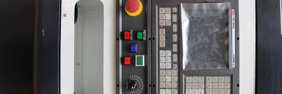
- Before operation, you must be familiar with the general performance, structure, transmission principle and control program of the CNC milling machine, and master the functions and operating procedures of the operating buttons and indicator lights. Do not operate and adjust the machine tool until you understand the entire operation process.
- Before starting the machine tool, check whether the electrical control system of the machine tool is normal, whether the lubrication system is unblocked, whether the oil quality is good, and add enough lubricating oil according to the specified requirements, whether the operating handles are correct, and whether the workpieces, fixtures and tools are firmly clamped , Check whether the coolant is sufficient, and then drive a slow car idling for 3 to 5 minutes, check whether the transmission components are normal, and confirm that there is no fault before it can be used normally.
- After the program is debugged, it must be approved by the instructor to operate according to the steps, and it is not allowed to skip the steps. Those who operate without the permission of the instructor or operate in violation of regulations will be treated with zero points for their scores, and those who cause an accident will be punished and compensated for corresponding losses in accordance with relevant regulations.
- Before machining parts, it is necessary to strictly check whether the machine origin and tool data are normal, and perform a simulation run without cutting trajectory.
Process Considerations
- When processing parts, the protective door must be closed, the head and hands are not allowed to enter the protective door, and the protective door is not allowed to be opened during processing;
- During the processing, the operator is not allowed to leave the machine tool without authorization, and should maintain a high degree of concentration and observe the running state of the
- machine tool. In the event of an abnormal phenomenon or accident, the program should be terminated immediately, the power supply should be cut off and the instructor should be reported in time, and no other operations should be performed;
- It is strictly forbidden to slap the control panel and touch the display screen hard. It is strictly forbidden to knock on the worktable, indexing head, clamps and guide rails;
- It is strictly forbidden to open the control cabinet of the CNC system to watch and touch without permission;
- The operator is not allowed to change the internal parameters of the machine at will. Intern students are not allowed to call or modify other programs not compiled by themselves;
- On the machine control microcomputer, no other operations are allowed except for program operation and transmission and program copying;
- The CNC milling machine is a large precision equipment. Except for the tooling and workpieces on the worktable, it is strictly forbidden to stack any tools, clamps, blades, measuring tools, workpieces and other sundries on the machine tool;
- It is forbidden to touch the tip of the knife and iron filings by hand. The iron filings must be cleaned with iron hooks or brushes;
- It is forbidden to touch the rotating spindle, workpiece or other moving parts by hand or in any other way;
- It is forbidden to measure the workpiece, manual speed change during processing, and not to wipe the workpiece with cotton thread, nor to clean the machine tool;
- It is forbidden to conduct trial operations;
- When using the handwheel or rapid traverse method to move the position of each axis, be sure to see the “, -” signs in each direction of the machine tool X, Y, and Z before moving. When moving, turn the hand wheel slowly to observe the direction of movement of the machine tool before speeding up the movement;
- When the measurement of the workpiece size needs to be suspended during the program operation, the standby bed must be completely stopped and the spindle can be stopped before the measurement can be carried out to avoid personal accidents;
- If the machine tool is not used for several days, the NC and CRT parts should be energized for 2-3 hours every other day;
- When shutting down, wait for the spindle to stop for 3 minutes before shutting down.
Status Quo And Prospects
Status Quo And Prospects
In 2012, my country’s economic development slowed down, and the lack of industrial growth had a major impact on the entire processing center industry. In modern society, the negative effects of overcapacity in the processing center industry began to appear. In the next stage, the industry will absorb a number of small manufacturers through mergers and reorganizations, eliminate a number of backward companies, transfer a number of processing centers abroad, and improve product quality. This not only solves the problem of overcapacity, but also improves the overall level of the processing center industry.
The downturn in the market has also brought transformation opportunities for processing center companies. Companies should shift their main energy from selling products to improving product quality, reset product lines, formulate development strategies, eliminate outdated products, and do more research and development. Processing centers with strong profitability are ready for the market to pick up.
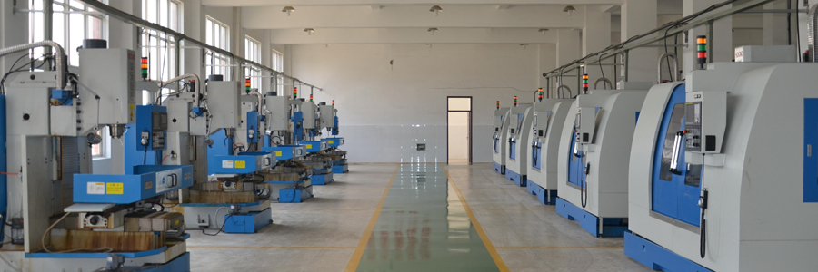
Benefiting from the country’s environment for revitalizing the equipment manufacturing industry and strong market demand, the domestic milling machine tool industry has seen rapid technological development and high investment enthusiasm. The “Twelfth Five-Year Plan” has made the revitalization of the equipment manufacturing industry the main content of promoting the optimization and upgrading of the industrial structure, and the CNC milling machine has become one of the focuses of the revitalization of the equipment manufacturing industry. In the future, my country will focus on the development of high-speed, precision, composite CNC metal cutting and milling machines; heavy-duty CNC metal cutting and milling machines; CNC special processing and milling machines; large-scale CNC forming stamping equipment and related parts of CNC milling machines.
In 2011, China produced 1.0984 million milling machines, achieving a total industrial output value of 660.65 billion yuan, a year-on-year increase of 32.1%, of which 272,100 CNC milling machines, a growth rate of 15.26%, have become the mainstream of milling machine consumption. In particular, high-end CNC milling machines belong to the high-end equipment manufacturing industry, with the characteristics of high technology content and high-tech added value. They are an important focus for the development of strategic emerging industries. The market for high-end CNC milling machines is huge in the future.
Basic Structure
|
Standard accessories:
|
|||
|
* Fully enclosed protective cover
|
* Spindle blow
|
* Three-axis telescopic shield
|
* Explosion-proof work light
|
|
* Electrical box heat exchanger
|
* Rigid tapping
|
* Operation and maintenance manual
|
* External handwheel
|
|
* Belt drive
|
* Program storage
|
* DNC computer transmission line
|
* Toolbox
|
|
* Cutting cooling unit
|
* Automatic lubrication system
|
* Three-axis screw pre-tensioning device
|
|
|
* Cutting air blowing device
|
* Horizontal bolts and spacers
|
* Three-color warning light
|
Precision milling
|
|
Optional accessories:
|
|||
|
*Fourth axis rotating table
|
*Stabilizer
|
*Spindle speed 10000/12000rpm
|
|
|
*Automatic tool length measurement system
|
*Chip conveyor
|
*Hat type tool magazine/disc type tool magazine
|
|
|
*Spindle oil cooler
|
*Water out of the spindle center
|
||
Please keep the source and address of this article for reprinting:Cnc Milling Machine
Reprint Statement: If there are no special instructions, all articles on this site are original. Please indicate the source for reprinting.:Cnc Machine Wiki,Thanks!^^